Description
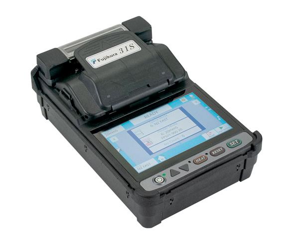
Fujikura 31S Fusion Splicer
The Fujikura 31S is a fully ruggedized, active cladding alignment fusion splicer. The dualcamera active V-groove alignment system provides consistent splicing performance in the most challenging conditions. A 6-second splice time and 25-second shrink time offers unmatched speed and productivity, while an easy-to-use touchscreen monitor provides simple and intuitive menu navigation. Interchangeable sheath clamps or fiber holders provide versatility for user preference, and compatibility with fusion-installable connectors. The extended-life battery is rated for up to 200 splice and heat cycles. Long-life electrodes, lasting 5,000 splices, help minimize downtime for replacement and stabilization. The large 5" monitor provides a crystal clear image, even in the brightest sunlight. Software updates are accomplished via the internet allowing users to quickly update their software as new splice programs become available.
Backed by the best service team in the industry, the Fujikura 31S is the ideal splicer to use when portability, ruggedness, and reliability are needed for your splicing application.
Features
Features
- Two-camera active v-groove alignment
- 5" touchscreen monitor
- Interchangeable sheath clamps and fiber holders
- Fully ruggedized for shock, moisture and dust resistance
- Extended-life electrodes, 5,000 splices, exchangeable without tools
- Long-life battery (200 splices/shrinks per charge)
Specifications
| TECHNICAL SPECIFICATIONS | |
|---|---|
| MODEL | 31S Splicer |
| APPLICABLE FIBERS | Single-mode (G.652 & G.657), Multimode (G.651), DSF (G.653), NZDS (G.655) |
| CLADDING DIAMETER | 125 μm |
| COATING DIAMETER | 250 μm up to 3 mm |
| FIBER CLEAVE LENGTH | 5 mm to 16 mm |
| TYPICAL AVERAGE SPLICE LOSS | 0.03 dB (SM), 0.01 dB (MM), 0.05 dB (DS), 0.05 dB (NZDS) |
| SPLICING TIME | Typical 6 sec with SM |
| ARC CALIBRATION METHOD | Automatic, real-time and by using results of previous splice when in AUTO mode; manual arc calibration function available |
| SPLICING MODES | Total 100 splice modes |
| SPLICE LOSS ESTIMATE | Based on two camera, active cladding alignment data |
| STORAGE OF SPLICE RESULT | 10,000 splice results |
| FIBER DISPLAY | 5 inch TFT color LCD with X or Y view or both X and Y view simultaneously |
| MAGNIFICATION | 200X for single-camera view and 132X for dual-camera view |
| VIEWING METHOD | 2 axis CMOS camera |
| OPERATING CONDITION | Altitude: 0 to 5,000 m above sea level, -10° to +50° C, Humidity: 0 to 95% RH, non-dew |
| MECHANICAL PROOF TEST | 1.96 N |
| TUBE HEATER | 30 heating modes |
| TUBE HEATING TIME | Typical 25 sec with FP-60 (60 mm) sleeve |
| PROTECTION SLEEVE LENGTH | 60 mm, 40 mm, micro |
| SPLICE/HEAT CYCLES WITH BATTERY | Typical 200 cycles with BTR-11 |
| ELECTRODE LIFE | 5,000 splices |
| POWER SUPPLY | Auto select from 100 V to 240 V with AC adapter, 14.8 V DC with installed battery |
| TERMINALS | USB 2.0 |
| WIND PROTECTION | Maximum wind velocity of 15 m/s (34 mph) |
| DIMENSIONS | 131 x 201 x 79 (mm) |
| WEIGHT | 1,300 g (2.85 lbs) with battery |
Additional Information
Fusion Splicing Process
The process of fusion splicing normally involves using localized heat to melt or fuse the ends of two optical fibers together. The splicing process begins by preparing each fiber end for fusion.
Stripping the Fiber
Stripping is the act of removing the protective polymer coating around optical fiber in preparation for fusion splicing. The splicing process begins by preparing both fiber ends for fusion, which requires that all protective coating is removed or stripped from the ends of each fiber. Fiber optical stripping can be carried out by a special thermal fiber stripper tool that uses hot sulphuric acid or a controlled flow of hot air to remove the coating. There are also mechanical fiber strippers used for stripping fiber which are similar to copper wire strippers. Fiber optical stripping and preparation equipment used in fusion splicing is commercially available through a small number of specialized companies, which usually also designs machines used for fiber optical recoating.
Cleaning the Fiber
The bare fibers are cleaned using alcohol and wipes.
Cleaving the Fiber
A fiber cleaver is then used to cleave the fiber using the score-and-break method so that its endface is perfectly flat and perpendicular to the axis of the fiber. The quality of each fiber end is inspected using a microscope. In fusion splicing, splice loss is a direct function of the angles and quality of the two fiber-end faces. The closer to 90 degrees the cleave angle is the lower optical loss the splice will yield.
Splicing the Fibers
Current fusion splicers are either core or cladding alignment. Using one of these methods the two cleaved fibers are automatically aligned by the fusion splicer in the x,y,z plane, then are fused together. Prior to removing the spliced fiber from the fusion splicer, a proof-test performed to ensure that the splice is strong enough to survive handling, packaging and extended use. The bare fiber area is protected either by recoating or with a splice protector. A splice protector is a heat shrinkable tube with a strength membrane.
What's In The Box
What's In The Box
- Qty 1 - Fujikura 31S Fusion Splicer
- Qty 1 - S31A Sheath Clamps (installed)
- Qty 1 - SP-31 Set Plates
- Qty 1 - ADC-19A AC Adapter
- Qty 1 - BTR-11 Battery Pack (installed)
- Qty 1 - FH-70-250 Fiber Holders
- Qty 1 - FH-70-900 Fiber Holders
- Qty 1 - ACC-09 Power Cord
- Qty 1 - ELCT2-16B Spare Electrodes (pair)
- Qty 1 - Operation Manual on CD
- Qty 1 - Quick Reference Guide
- Qty 1 - SS-03 Single Fiber Stripper
- Qty 1 - CC-35 Transit Case